
The marquee design assignment for this week definitely took a lot longer than I expected! The schematic I used was slightly adjusted from the one Andy shared in class, seen below:
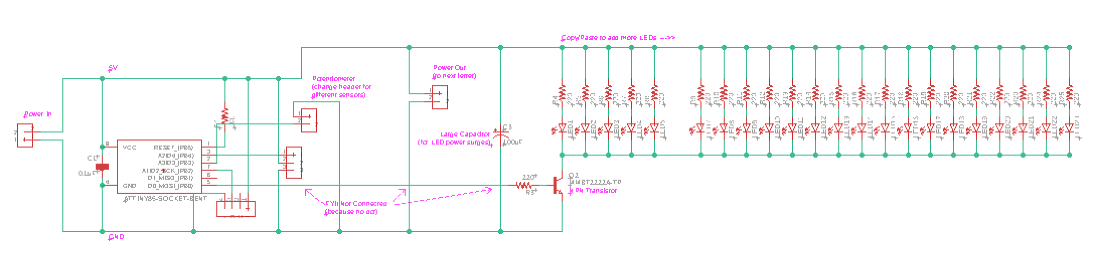
I was assigned the letter M. Arranging and connecting everything was quite the challenge, especially since James and I decided to coordinate the interactions on our board using RF signals. This meant that we had to make adjustments to Andy’s schematic in order to incorporate both an RF reciever and transmitter (in addition to a simple switch for base interaction with the LED lights).
The final design looked like this:
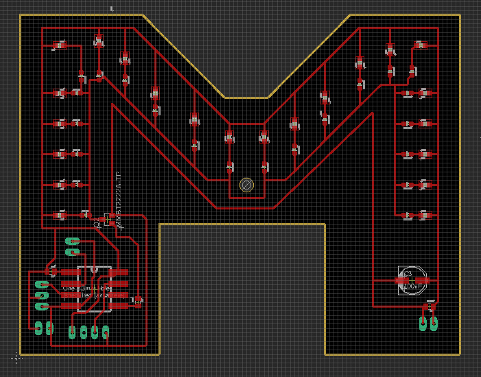
I used header pins where the RF modules would go (in case I wanted to replace them for any reason).
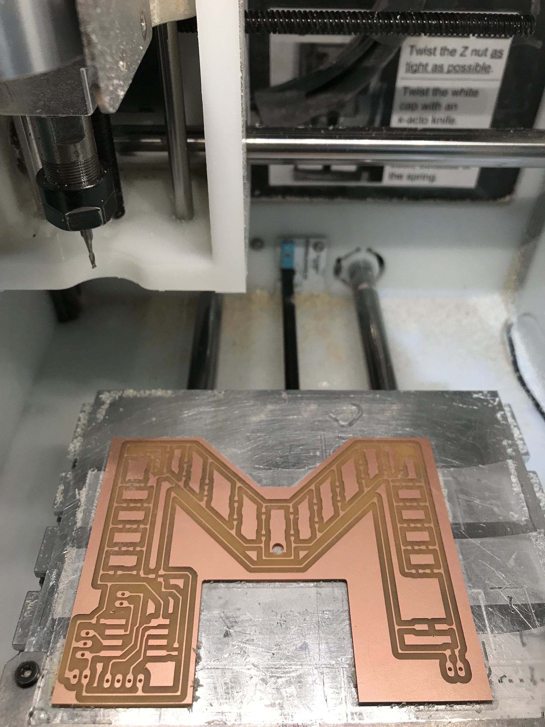
Milling and soldering the board was not as bad as I expected, given how intimidated I was by the Othermill at first. It was actually pretty fun!
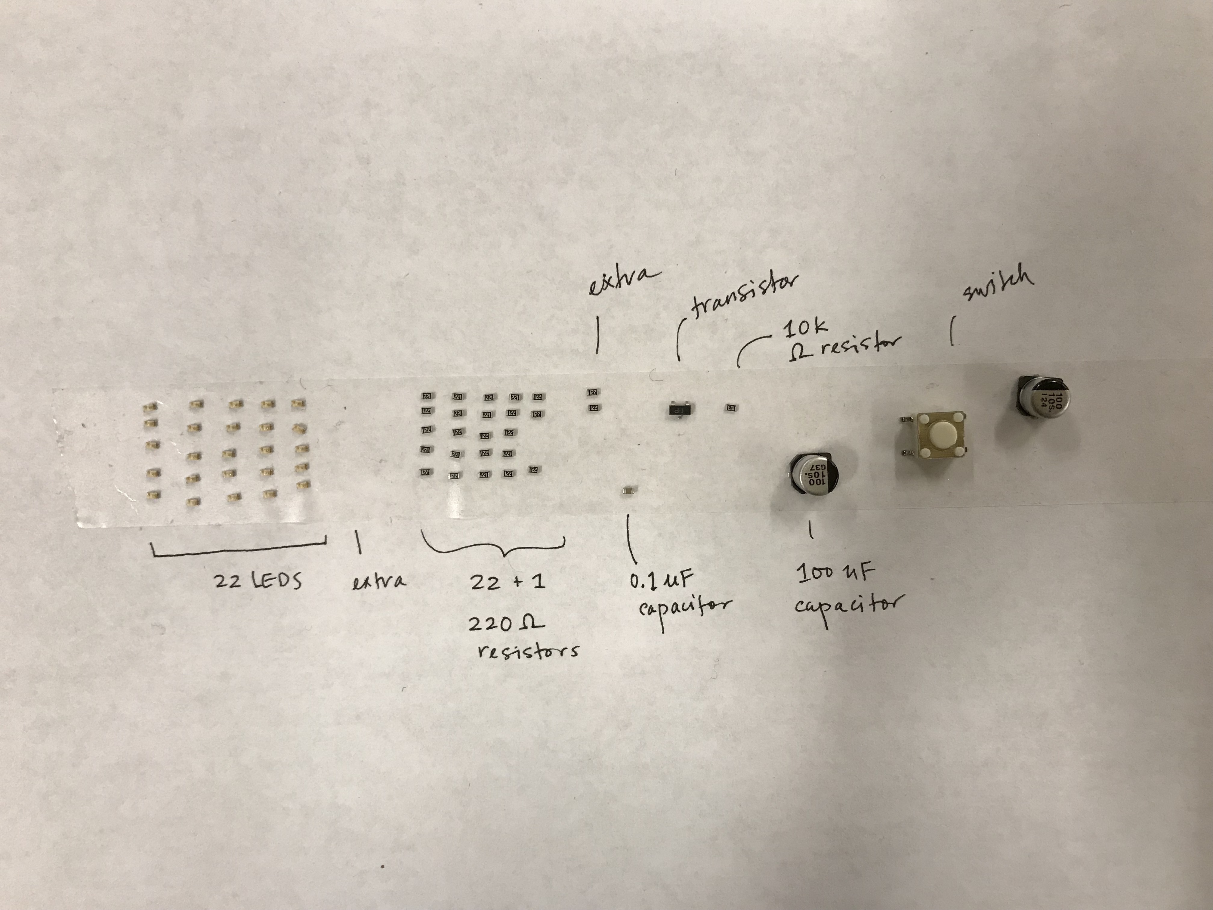
(The label on the parts for LEDs is not completely accurate – I have 25 LEDs there, and did not separate our the 3 extra LEDs as my markings would suggest).
You can view the simple button press interaction here:
It seems that my button sometimes gets stuck in a down position, but I enjoy it.
James focused on coding RF interactions. His code, roughly based on this tutorial: Instructable. This particular iteration of our code relies on a library called Manchester, which seems to work well with the limitation of the ATTiny’s memory. (Previously, James had experimented with a Radiohead, yet another another RF library, but this ran into issues on the Tiny).
When I had experimented with the version of the code from this tutorial, I ran into quite a bit of trouble detecting why it wasn’t working. (It’s quite hard to detect whether your transmission is sending if you’re not sure if your receiver is working). A key difference between the code I been using and the code below was this line: man.workAround1MhzTinyCore();. (And James has also structured his code nicely to handle RX and TX events in separate functions).
#include <Manchester.h>

#define RXPIN 2       //<< RADIO RECEIVE PIN
#define TXPIN 4       //<< RADIO TRANSMIT PIN
#define LEDPIN 0      //<< PIN FOR LED TRANSISTORS
#define BTNPIN 3      //<< PIN FOR BUTTON


bool ledState = false;
bool triggerState = false;
int t_msg = 0;
int c = 0;

void setup()
{
  pinMode(LEDPIN, OUTPUT);
  pinMode(LEDPIN, OUTPUT);
  pinMode(BTNPIN, INPUT_PULLUP);       //<< PIN FOR BUTTON/SWITCH

  man.workAround1MhzTinyCore(); //add this in order for transmitter to work with 1Mhz Attiny85/84
  man.setupTransmit(TXPIN, MAN_1200);

  man.setupReceive(RXPIN, MAN_1200);
  man.beginReceive();


  //Startup Seq, things are A-Okay!
  for (int i = 0; i < 5; i++) {
    digitalWrite(LEDPIN, HIGH);
    delay(100);
    digitalWrite(LEDPIN, LOW);
    delay(100);
  }
}


void loop()
{

  handleTX();
  handleRX();
  handleLEDs();
  if (c == 10000) {    //<< Repeat for redundancy
    sendMessage();
    c = 0;
  }
  c++;

  delay(5);
}

void sendMessage() {
  man.transmit(t_msg);
}

void handleLEDs() {
  if (ledState) {
    digitalWrite(LEDPIN, HIGH);
  } else {
    digitalWrite(LEDPIN, LOW);
  }
}

void handleRX() {
  if (man.receiveComplete())
  {
    uint8_t r_msg = man.getMessage();
    if (r_msg == 1) {
      ledState = true;

    } else if (r_msg == 2) {
      ledState = false;
    }

    man.beginReceive();
  }
}


void handleTX() {
  if (digitalRead(BTNPIN) == LOW) {          //<<Button ON
    if (triggerState == false) {        //<<Ensure triggered only once
      t_msg = 1;
      sendMessage();
      triggerState = true;              //<<Ensure triggered only once
    }
  }
  else {                              //<<Button OFF
    if (triggerState == true) {         //<<Ensure triggered only once
      t_msg = 2;
      sendMessage();
      triggerState = false;             //<<Ensure triggered only once
    }
  }
}
Another important difference between our two tests may have also been antenna design. In my initial tests, I was just using the antennas on board the RF modules. James, when our initial tests with various libraries failed, attached a seperate antenna to the board and we had much more reliable success after this point.
We still need to test and document our final interaction between our board, but initial tests seem promising for our printed and newly coded versions.