
For my final presentation in Energy, I had created some slides to explain how the 555 timing chip worked, but based on the advice of smart people, I decided not to bore my audience with the details during the actual presentation. However, I thought I’d share the slides here (perhaps, mostly for my own sake, for my later reference.).
The hand-drawn portions of the image represent the actual circuit design we used for the Growver project.
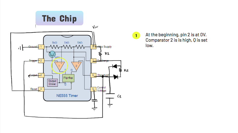
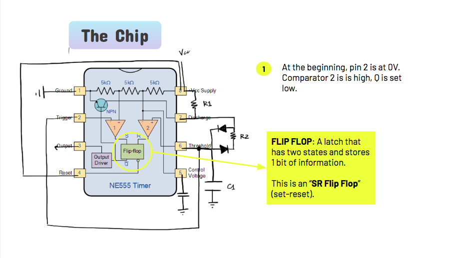
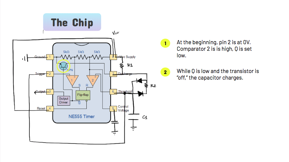
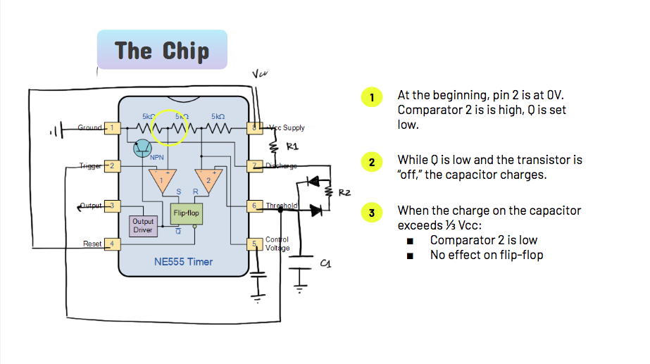
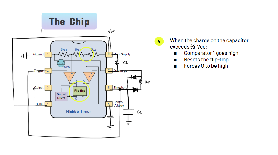
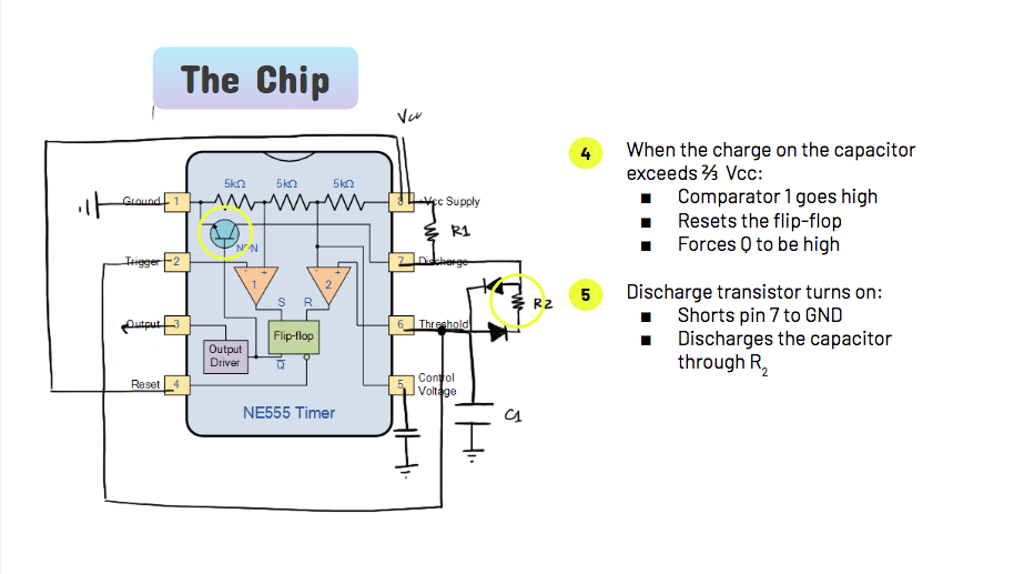
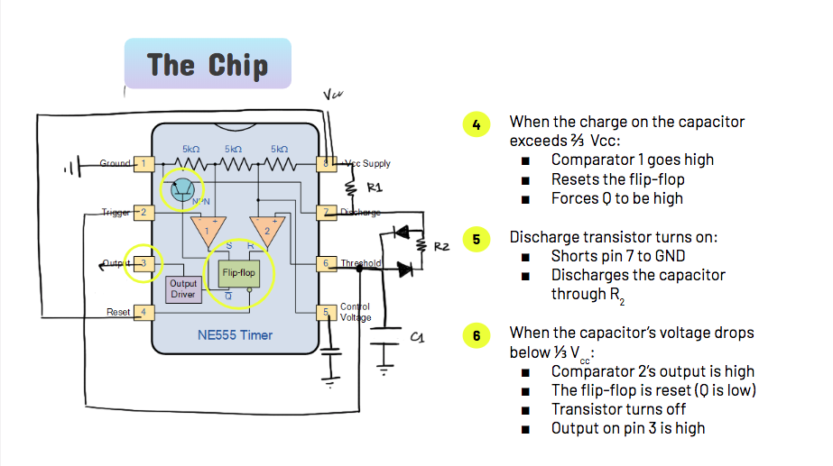
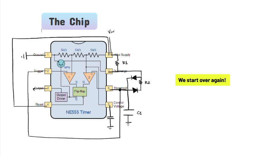
The slides are based on my notes from Practical Electronics for Inventors.