
Last week, James Hosken and I wrapped up “Growver”, a roaming solar-powered bot that seeks sunlight to power itself. For our Energy midterm, we had presented an early version of Growver that functioned that was missing an intregration with a key power-saving mechanism I had been working on: a 555 timing circuit.
Here is it in action back then:

It should be noted that Brent Bailey was also working on the project with us at the time, and made valuable contributions in both the fabrication of Growver and its direction-finding code.
For the final, James and I decided to split up the work so that I focused on the 555 and he worked on robot behavior.
I had based my timing circuit on an oscillator tutorial, and need to make a key change to include a relay:
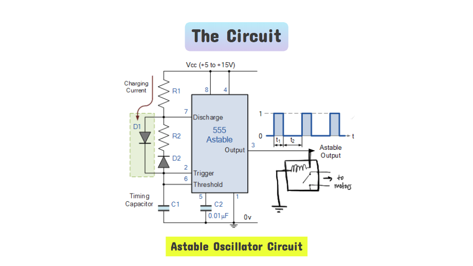
(For those interested, I wrote up some additional information the IC here: About the 555).
For the midterm, we had attempted to make the 555 trigger a transistor, but had into some trouble due to its placement within the rest of the circuit. We consulted Eric Rosenthal, with whom we had taken Basic Analog Circuits, and he had recommended simplifying matters by switching to a relay.
Unfortunately, we still ran into some trouble with the circuit – though the timing compontent worked over loads such as an LED, its behavior became quite erratic when triggering the relay. For my Homemade Hardware final, I had designed an PCB with the timing circuit, and for a great deal of time, believed that the erratic behavior was either due to my circuit design or soldering. I sunk quite a bit of time reconfiguring my circuit in Eagle and reprinting my PCB.
Fortunately or unfortunately, the errors were not due to my actions in designing the PCB or soldering it, but rather, a more fundamental error in my understanding of the relay in my timing circuit.
Because Eric had suggested the relay in the first place, I sent him a desperate email to update him on the behavior of my timing circuit. After a few messages back and forth, he asked which 555 chip I was using: I had poppped in the 555CN because that is what is stocked in the ITP shop, but unfortunately, this is a low-power chip was not providing enough power to trigger the relay consistently.
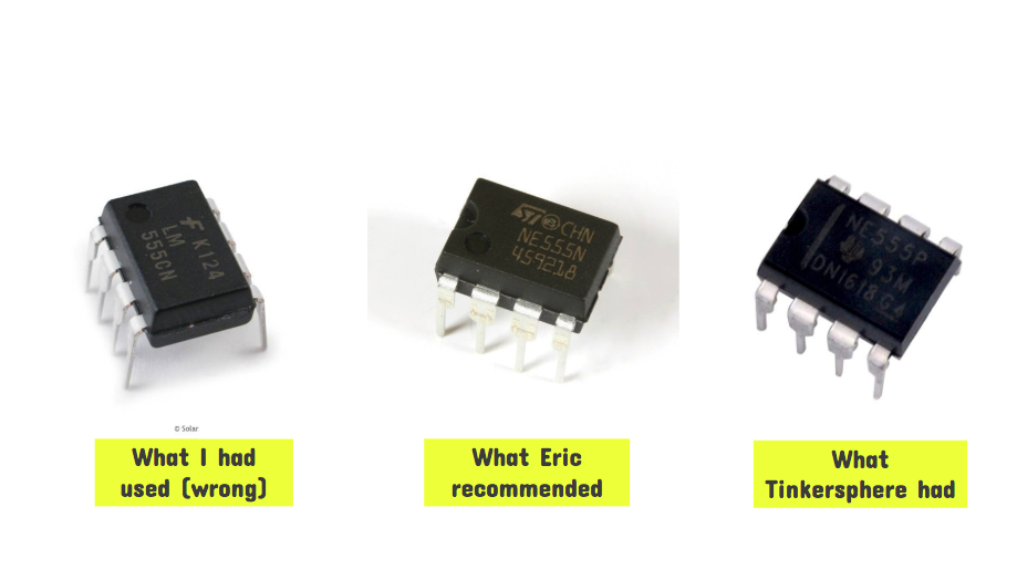
Thankfully, I was able to find a 555P in Tinkersphere.
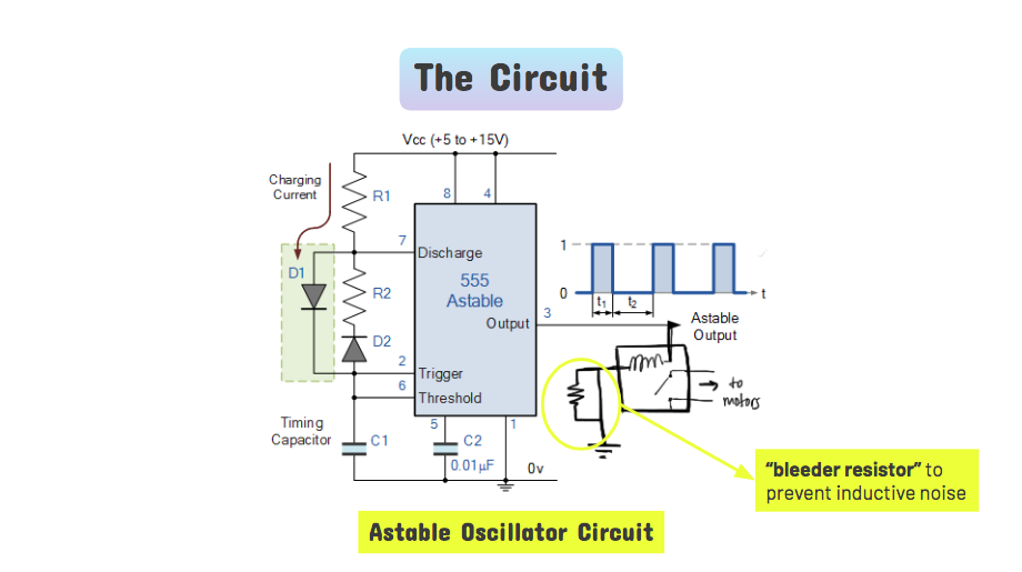
I had in passing complained in David Rios that nothing was working in my circuit, and he also took a quick look at what I had done so far. He suspected the magnetic coil in the relay may have been holding a inductive charge longered than it seemed on paper. He suggested that I add a pull-down resistor (in this case, called a “bleeder resistor”) to ground so that the coil could discharge when it was not powered.
The bleeder resistor, along with the new 555 chip, all within the span of a hour, solved the problem that had plagued me for days. The new circuit looked like this:
At this point, we connected the timing circuit to James’s motorshield + Arduino setup, and hoorah, it finally all worked well altogether.
At this point, the timing circuit had a 47k ohm and a 680k ohm resistors, yielding a duty cycle of approximately 1 minute on, 9 minutes off. The timing circuit was independently powered from 4 AA batteries. Based on that, my understanding of the current draw of the timing circuit and the life span of the batteries is calculated below:
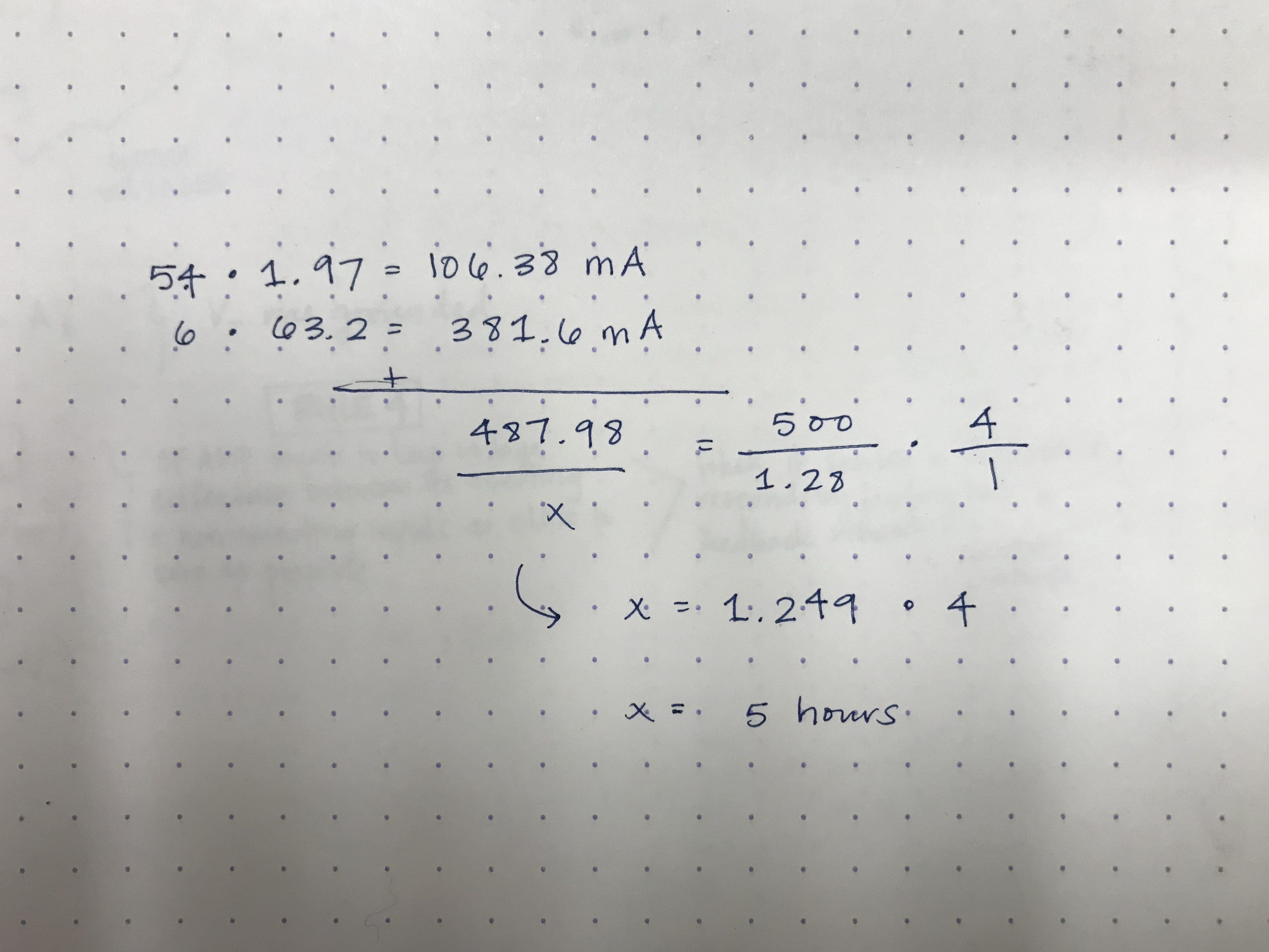
The current configuration is less than ideal, but it should be noted that in earlier iterations of the project, we had much larger resistors that allowed us to power on for 3 minutes and then off for 90. Now that the timing circuit and motors can function together, it is a minor change to adjust to a new, more energy-efficient duty cycle.
In the video below, you can see Growver in action. Its light-seeking behavior leaves something to be desired, but the timelapse allows you to see the timing circuit at work.