
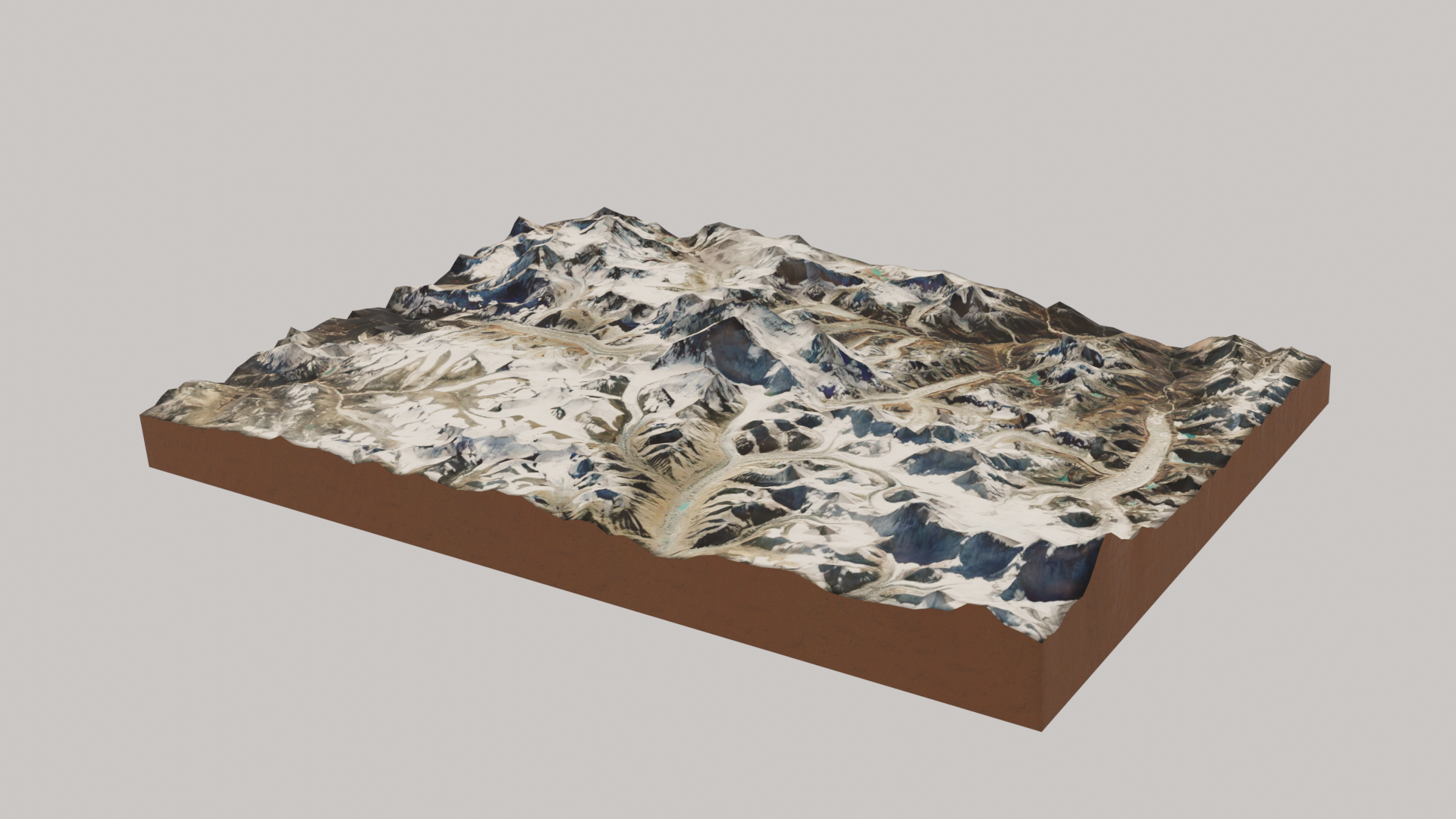
An! actual! render!, thanks to James Hosken. It turned out that my main problem was that the clipping plane of my render camera was much too small to capture the scene the way I wanted. I bumped up the clip end value 1,000,000 m (lol very large mountain range, so…), and this solved my main problem from Thursday. I also needed to change the clip end value of my viewport camera (basically a virtual camera), and then could navigate around as normal to frame the view I wanted. Importantly, I had to have “Camera to view” checked off in View settings. James noted a very helpful keyboard shortcut: hit ~ and then “View Selected” (assuming your active object is your plane/map object). This will bring your selected object to view! And James noted that you could also go into Edit Mode to select specific vertices, and then bring those into view.
Anyway, hire James Hosken for all the things.
This was so fun to make that I’ve captured my notes from the CG Geek tutorial I watched below, so I can quickly references steps and shortcuts in the future.
Adding the GIS data:
- Add basemap from GIS menu (
GIS -> Web geodata -> Basemap) gto search for specific location- Line up specific view using your
MMB - Once you’re happy with your view, hit
eto make the plane w. the mapped texture - Next,
GIS -> Web geodata -> Get elevation (SRTM)– elevation data will be added as a Displacement modifier.
Improving the mesh:
- In edit mode, subdivide the mesh a few times to bump up the quality.
- If it looks jagged, edit the texture in the Displacement modifier by switching Interpolation to on under Sampling.
- Then, apply the modifiers!
Adding depth:
- In Edit Mode, select all, and hit
eto extrude. - Next, hit
s + z + 0. This last part is to give that extrusion a flat bottom. - Another important keyboard shortcut:
F3to search! CG Geek has us search for for “Recalculate Normals” at this point.
Adding lighting, background:
Missed this in my first pass, but you can pull in an HDRI as an Environment texture (under World settings), and then, under Render settings, under Film, set it to transparent (this way, you keep the lighting!). Too cool!
Editing our material:
CG Geek then added a Bump node (connecting color output to height, normal to normal on our Principled BSDF node); this added some subtle texture for me! I think the effects could be more pronounced if I were working at a smaller scale.
He also added an Ambient Occlusion node, with a high distance (25ish), directed into a Power node and then to a Multiply node, which could take in two colors as inputs. One of the inputs was still from our satellite image, and the other from that Power node. Both went into Base Color of our Principled BSDF shader.
Adding the dirt material:
Next we created a new material, that we began to edit in Shader editor. We hit Ctrl + Shift + t to import a PBR material (texture we used). Then, we assigned the material to the edges by using face select in Edit Mode, and then alt + clicking to grab that loop cut. Then, we hit u -> Smart UV Project to unwrap the material. CG Geek made some adjustments to scale and coloring of this material, but I kept my edits pretty minimal at this point.
I’m so impressed with how easy BlenderGIS has made it to play with GIS data in Blender, and hope to dig into this more.