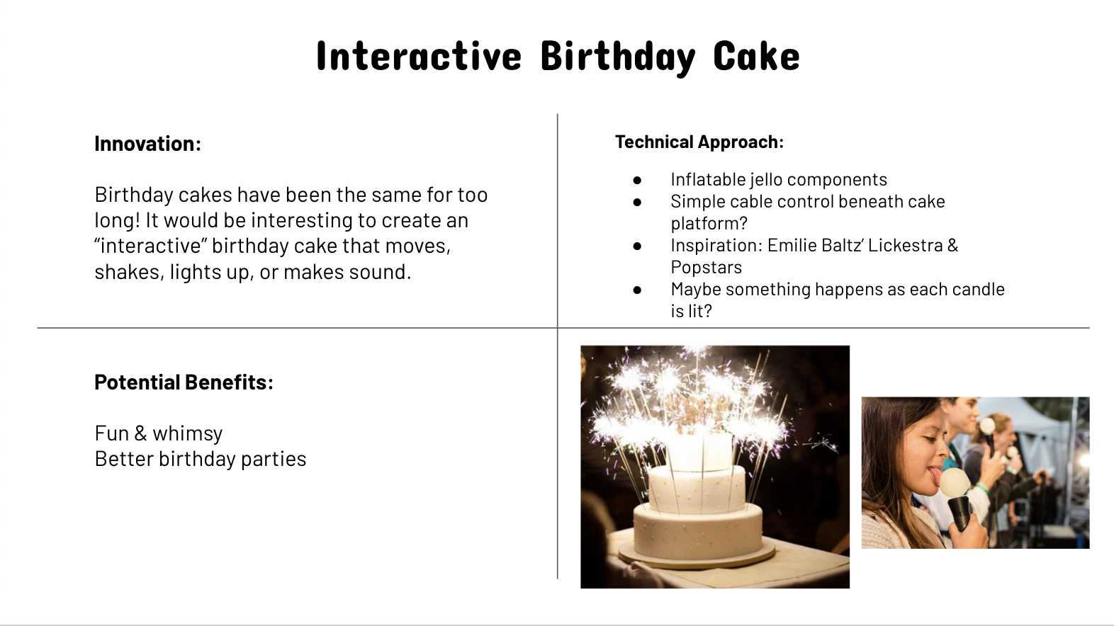
A very preliminary quad chart of a final project idea:
And a sketch:


A very preliminary quad chart of a final project idea:

And a sketch:

#soft_robotics This week, I decided to make a variation of the mold we used last week. My silicone cast had a lot of room for improvement, and I wanted to iterate before I moved along completely from the base design.
I researched some of the possibilites of how I might adjust that design to yield a different kind of actuation. I was particularly interested in the internal restraints I could introduce to the design. In my research, I came across fiber-reinforced actuators in the Soft Robotics Toolkit. These actuators consisted of a flexible bladder that were wrapped with inextensible fibers, or thread, to constrain radial expansion.
The site suggested that the the following arrangement would result in an axial expansion (rather than the typical radial expansion we see in other balloon-like actuators):

In order to implement this design, I decided to use a two part casting process. Initially, I covered the inner mold from last week in silicone (using less than 5g of mixtures A and B each). I allowed this to cure until the surface was squishy to the touch.

Next, I wrapped thread in a double-helical pattern around the length of the inner mold.

Then, in a fill and degas process similar to the one utilized last week, I placed the inner mold in the outer mold, this time working quickly enough that the mixture was significantly less viscous than last week’s iteration at this stage of fabrication.

I then allowed the whole mold to cure overnight.
[I’ll update with a video, once I’ve tested its behavior with an air pump.]
#soft_robotics I’m hoping to combine my final for Homemade Hardware with my final for Energy. James and I are constructing a solar-powered rover that seeks light. My work on the rover has focused on the use of a 555-timing circuit. The circuit is based on this tutorial: 555 Oscillator Tutorial.
The schematic I’m interested in can be seen below:
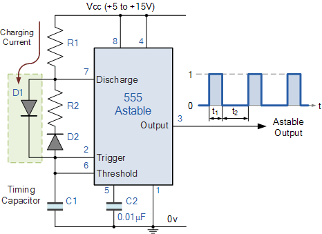
I’ve breadboarded this particular circuit a million times, but I would be very interested in having an Eagle design of this circuit because I think it can be useful in many applications beyond our solar rover. Essentially, it would allow me to power any load for a given amount of time (and then be off for a given about of time, as per my RC duty cycle).
I would like to keep R1, R2, and C1 modular, so I would likely put in header pins in place of those components.
BOM:
#homemade_hardware This week, we were supposed to cast a mold to create a silicone bibenda actuator. This assignment was definitely challenging for me, as I am not the best fabricator. I’ve included some of my process photos below, along with some notes on what went wrong.
I’m hoping to do a second cast early tomorrow morning to see if I can produced a better second version, because this one was bit of a disaster.
I 3D-printed the inner mold, but foolishly forgot to take process photos.
For the outer mold, I actually found a piece of PVC pipe that was the correct size, but as I had never used a pipecutter before, I decided to cut another piece anyhow.

Proof!:

For a while, I unable to glue the out mold together because I could not open the PVC primer or cement. I had to enlist the help of a friend with a wrench(?).

This is how the outer mold came together:

Next, I cut some stretch fabric to fit it over the inner mold, as per the instructions. There are no words:

I then began to mix part A and B. I realized I was moving too slowly too late. The first degassing can be seen below:

This shows the second degassing. It’s a bit too difficult to see in the picture, but there were way too many air bubbles, and because of how think the mixture had gotten, a lot of it was spilling over the edges. That seemed to be my biggest error: I had allowed the mixture to get too thick by the time I was pouring it into the mold. This meant that 1) it was really difficult to poor into the small mold at all, and 2) I introduced many air bubbles trying to get the mixture inside.

Bit of a mess, but here is the setup at rest:

It did not come out very well. There are VERY large air bubbles near the gaps in the stretch fabric.

If there’s time I’d love to redo this one. I know my error: I took way too long to coat the inner mold, degas, and pour. I was also reading and rereading the instructions to make sure I was doing things exactly right (even though I read the instructions prior to starting, I was a bit paranoid about missing something). Ironically, that did me in.

#soft_robotics Our field trip to the Materials ConneXion library was really interesting. I found a few items particularly exciting:
1) Veilshield (link)

Veilshield is a mesh conductive fabric with stated applications for electromagnetic interference and field shielding. I’m very curious to understand how these fabrics maybe be layed with clothing, and how to test its shielding capabilities. In previous wearable projects that involved a capacitive touch sensing over conductive fabric, I ran into some EMF interference issues. I’m curious how layering this fabric with non-conductive layers would better my previous designs. The fabric itself is quite flexible, but not very stretchy. The manufacturer is apt named Less EMF Inc, and the material can be bought from directly from them.
2) Textile-based Conductors (link)
This is a conductive silver-ink that can be inkjet-printed onto fabric to create highly conductive traces. The limitations of this product seems only to be the imagination of the designer. Applications noted by the manufacturer include: ECG monitoring and other medical/fitness sensing, interconnects, proximity sensors, and capacitive touch sensors. The manufacturer is Liquid X Printed Metals, and the ink can be purchased directly from them.

I’m most interesting in creating subtly “smart” wearables, and these items fit that bill.
#soft_robotics